ddr
DDR Pad
Norman Chung, Andrew Lu.
ECE 153B, Winter 2020, Professor Isukapalli.
DDR Pad Demo Video: https://youtu.be/8BjvtFz74WU
Overview
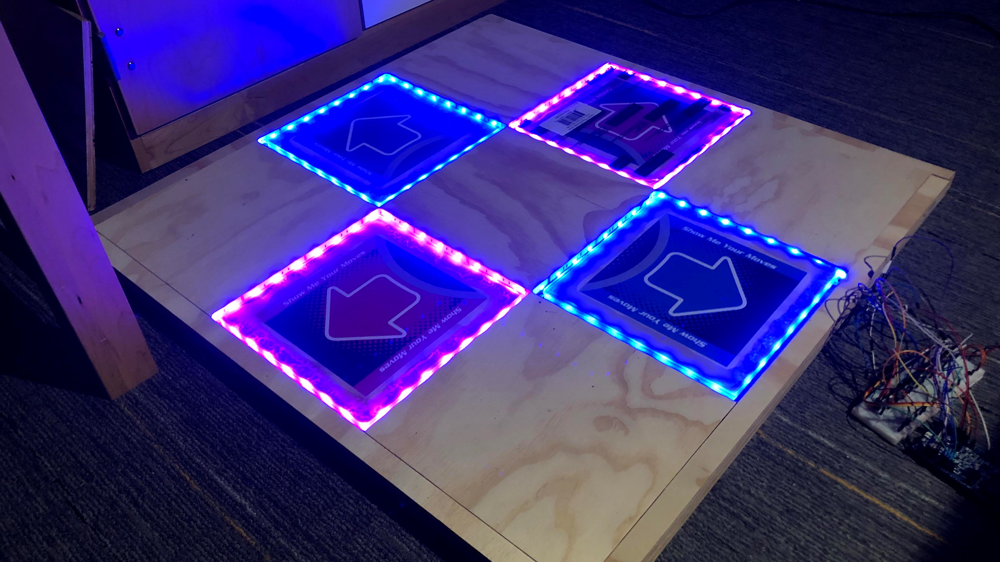
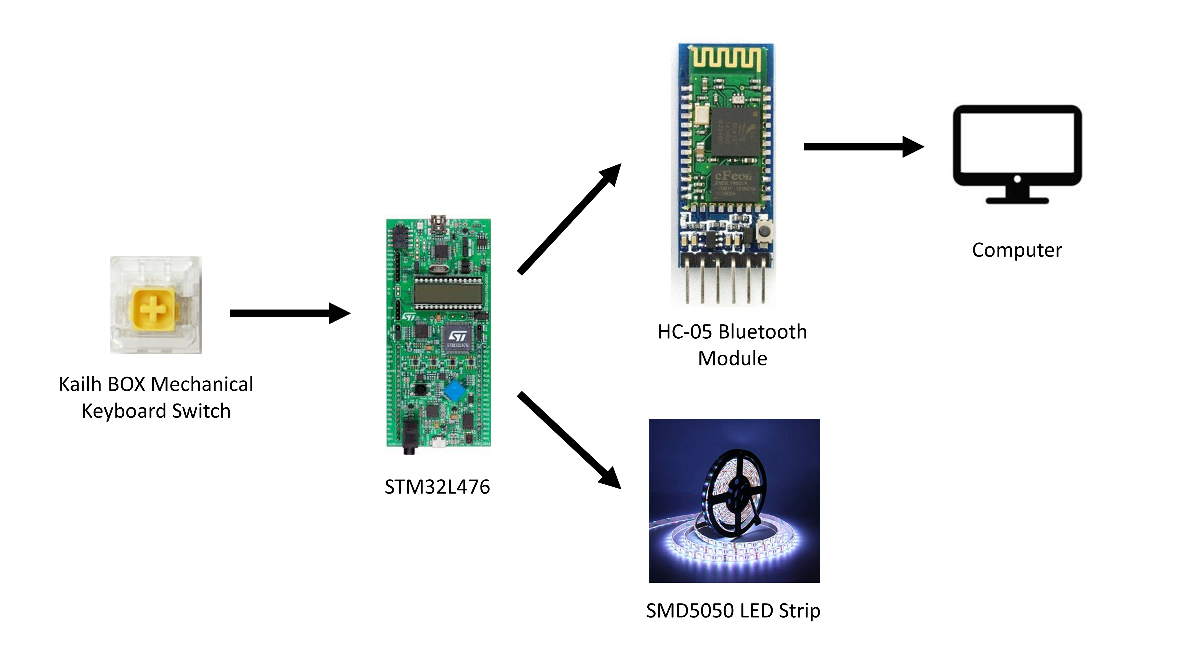
The goal of this project is to create a dance pad designed to play the “Dance Dance Revolution” game commonly found in arcades. The dance pad will consist of a large 3x3 grid with up, down, left, and right arrows which will serve as large buttons. When playing the game, users can step on the large buttons, which will cause an interrupt to send a keystroke over Bluetooth to the computer running the game.
Parts List
| Part | Quantity | Unit Price | Total Price |
|---|---|---|---|
| STM32L476 Discovery Board | 1 | $25.00 | $25.00 |
| HC-05 Bluetooth Module | 1 | $10.90 | $10.90 |
| NovelKeys x Kailh BOX Heavy Switches, Dark Yellow (Pack of 10) | 1 | $3.00 | $3.00 |
| Confined-Space Conical Compression Spring, 0.375” Long, 0.6” x 0.281” OD | 16 | $0.98 | $15.68 |
| SMD5050 Chipset 150 LED RGB Strip (12V) | 1 | $7.77 | $7.77 |
| Sanded Plywood (15/32 in. x 4 ft. x 8 ft.) | 1 | $29.45 | $29.45 |
| 12 in. x 24 in. x .093 in. Clear Polycarbonate Sheet | 2 | $15.98 | $31.96 |
| IRLZ34NPBF Logic-Level MOSFET | 12 | $1.04 | $12.48 |
| 12V 2A DC Power Supply | 1 | $7.99 | $7.99 |
| DC Power Cable Female Connector Plug (Pack of 10) | 1 | $5.87 | $5.87 |
| TOTAL | $150.10 |
* All prices are listed before taxes, tariffs, and shipping costs.
Peripherals
- 4-8 custom-made button pads
- The button pad will consist of a large piece of wood and polycarbonate connected to a mechanical keyboard switch and separated by springs. When the pad is compressed by a user stepping on it, the wood will push the keyboard switch, triggering an interrupt.
- HC-05 Bluetooth Module
- Used to send keystrokes to a host computer.
- Communicates with the STM32 board using UART.
- LED Strips (SMD5050 chipset)
- Layered on the side of the pads, so when a user steps on it, the strip lights up.
- Wood, Polycarbonate, and Springs for the assembly of the pad.
- Computer (used to play osu!mania, a rhythm game used to simulate “Dance Dance Revolution” with the Stepmania skin)
External Pin Connections
- PB7 - HC-05 Tx
- PB6 - HC-05 Rx
- PA0 - Up Button Input
- PA1 - Down Button Input
- PA2 - Left Button Input
- PA3 - Right Button Input
- PB3 - Up Red
- PA5 - Up Green
- PD0 - Up Blue
- PC14 - Down Red
- PC15 - Down Green
- PH0 - Down Blue
- PH1 - Left Red
- PE11 - Left Green
- PE10 - Left Blue
- PE12 - Right Red
- PE13 - Right Green
- PE14 - Right Blue
Software Design
- Each of the switches will be connected to a GPIO input pin. When the user steps on the pad, the circuit in the pad will be connected and trigger the interrupt for that GPIO pin.
- If the interrupt is caused by a rising edge (stepping on the pad), the interrupt handler will send a message to the computer via the HC-05 bluetooth module stating that the pad has been pressed and a keyboard press should be emulated.
- When the user steps off the pad, the interrupt caused by the falling edge will send another message to the computer stating that the pad has been released and the keyboard press should be stopped.
- In addition, when the interrupt is triggered, we will light the LED strip to match the color of the button pad. When the user steps off, the LED strip turns off.
Block Diagram
Goals
- Construct 4 button pads capable of withstanding continued footsteps (in a way that will not ruin the springs or the switches in the long run).
- Create an interrupt, triggered on both rising and falling edges, to translate pad steps to keypress messages communicated over Bluetooth to the computer running the game.
- When reading in the rising edge or falling edge, change the state of the LED lights accordingly.
The original project proposal, submitted to GauchoSpace, can be found here.
Weekly Updates
Week 6 Update (February 14)
After an initial review by our TA (Ryan Kirkpatrick), along with some additional research about ways to implement our large button pads, we have decided to make the following changes to our project:
- Instead of using foil pads for our large buttons, we will look into using mechanical keyboard switches (specifically NovelKeys x Kailh BOX Heavy Switches, Dark Yellow), since they have two legs and can be connected like a regular button.
- We have purchased two packs and will be testing this with our board once we receive them.
- The NFC functionality for inserting credits will be moved to the end of our project and set as a stretch goal, upon recommendation from Ryan, since I2C communication for the PN532 module has the potential to cause a lot of issues.
- If time permits, we will try to implement this functionality, but it will be put on the side for now.
- We will initially start with only four large button pads for the four directions. The “Select” and “Back” buttons will either be added in later or simply be smaller buttons on the side.
Week 7 Update (February 21)
We have received our initial order of mechanical keyboard switches. We were able to wire them like buttons and successfully use them to trigger interrupts by reading standard GPIO input.
The switch was connected as follows:
- One leg of the switch is connected to the 3V3 pin on the Discovery board.
- The other leg of the switch is connected via a breadboard to GPIO pin PB2 and one leg of a resistor.
- The other leg of the resistor is connected to GND.
When the switch is pressed, the two legs will be connected, allowing current to flow. The GPIO input pin reads the voltage after the switch and uses its state to trigger an interrupt.
This circuit was tested using the code from Lab 1, Part B. No changes were made to the code, and the circuit works as expected, so we will move forward with using mechanical keyboard switches to detect steps on our DDR pad.
We plan to perform the following tasks this weekend:
- Finish Lab 3 (which will allow us to better understand the operation of the HC-05 Bluetooth Module).
- Create / sketch the design for the DDR pad. This includes the wood base, springs, switch placement, wiring, LEDs, etc.
- Create a list of parts we will need to purchase, and come up with a plan for purchasing these parts.
- Using the code from Lab 1, Part B, as a start, write the code and interrupts for the four switches that will be used.
Week 8 Update (February 28)
We started this week by completing Lab 3. In doing so, however, we discovered that the HC-05 Bluetooth Module is unable to act as a HID device. Upon researching this issue, we discovered that it is theoretically possible to flash the firmware on the module to allow the module to act as an HID device (see this Instructables article), but doing so would require us to buy an additional breakout board just to flash the new image. We simply didn’t have the time to purchase it, so we looked for other options.
As a result, we decided to forego emulating a Bluetooth Keyboard. We will instead use standard UART communication over Bluetooth, like we did with Lab 3. In order to get our pad presses into the StepMania app, we wrote a simple Python script that will read input from the COM port that the HC-05 is connected to, and emulate a keypress using a library such as pywin32 or pyautogui.
During Wednesday’s lab session, we combined parts of Lab 1B and Lab 3A starter code to use one of our mechanical keyboard switches to emulate the keypress of the character “a” on a computer. The code can be found on GitHub.
We have also started to plan the design and come up with a list of materials that we need. This image shows the preliminary sketches we made during Wednesday’s lab session for the design of the pad. We agreed to purchase the springs from McMaster-Carr and purchase the rest of the components from Home Depot. The exact list of components will be decided over the weekend, when we can create a more exact design.
Week 9 Update (March 6)
We started the week by creating the above parts list with all the parts we already ordered. During Wednesday’s lab section, we then researched the hardware materials we needed to purchase from Home Depot, and have added those new materials to the parts list as well. We have also ordered a set of 15 logic-level MOSFETS for driving the LEDs using the GPIO output, which will arrive on Monday.
On Thursday night, we made a trip to Home Depot and purchased all the necessary supplies for our project. We were able to cut our plywood into a 35 inch by 35 inch square base and the 11 inch strips for creating the pads, but due to store limitations on the number and size of cuts we were able to make, we were unable to have their associates make every cut that we needed. As a result, we plan to finish cutting the rest of the board on Tuesday at the UCSB Woodshop in the Arts building.
We do not plan on doing any further work this weekend due to numerous assignments and the 153B midterm on Monday. We will provide new updates after that.
Week 10 Update (March 13)
We started this week by getting the rest of our wood cut at the Woodshop. Once that was completed, we spent one night gluing together the borders and corner tiles. We also spent some time fixing our Python script for emulating keystrokes. When playtesting our circuit, we discovered that StepMania does not support virtual keypresses, so we have opted to use osu! from now on. The build stream can be found here.
In our next meeting, after verifying that the borders and corner tiles were glued together, we cut the polycarbonate and trimmed the borders to size. Once that was complete, we glued three of the borders and corner tiles to the base. We also glued the springs to each of the button pads. The build stream can be found here.
As we both have other projects that are due this weekend, we won’t be meeting again until Finals week. Our plan for finals week includes finishing the frame assembly (including LEDs and polycarbonate), and finishing our circuit.
Week 11 Update (March 20)
We started this week by wiring and soldering the entire circuit to the base of the DDR pad. This includes wiring up the LEDs and mechanical keyboard switches. We printed out DDR pad arrows and glued them to our polycarbonate tiles. Once that was complete, we drilled holes to fit our keyboard swtiches, and finished the assembly of the DDR pad by gluing in the center tile and the final border. We also finished coding our LED strips, though we were not able to test them in this meeting as we were waiting for the glue on the keyboard switches to dry. The build stream can be found here.
In our last meeting, we wired up the final circuit, tested the LEDs, and glued the springs to the base. We then proceeded to play osu!.